Designing radiant (ceiling, wall) panel heating/cooling systems
| Product | InstalSystem 5 |
| Type of article | DESIGN APPLICATION |
| Source for translation | IS 5.0 Beta 33 |
Scope of lesson
This article presents the manner of designing radiant systems where prefabricated ceiling and wall panels are used for the purpose of heating or cooling.
Modules and program configuration
- InstalSystem 5 package containing the module:
- Panel systems
Inital state
A design that includes the structure of the building (storeys, rooms) along with storey plan. The values of design heat load of rooms are defined for heating and cooling.
Steps to perform
Loading catalogues and setting default design data
General data window
| Project files
|
Initial state, isproj Panel system installation in a public building, isproj |
| Designed with | InstalSystem 5 Rev. Beta 33 |
| Required modules | InstalSystem basis Radiant heating system 5 Radiant cooling systems 5 Radiant panel systems 5 |
| Project range | Radiant heating and cooling |
| Used catalogues |
Basic radiant systems |
| Type of building | commercial building with basement 2-storey |
| Building structure | Base drawing ground floor, dwg Base drawing first floor, dwg |
| Drawings range | Plan view |
| Prepared by | www.instalsoft.com |
| Legal disclaimer | The whole file or parts of the project may be copied |
| Calculation results | Full printout, xls Full printout, pdf General heating and cooling results, pdf Bill of materials, pdf Installation parameters, pdf |
| Drawing results | Basement, dwg Ground floor, dwg Basement, pdf Ground floor, pdf |
- Project scope tab - define design scope: Heating systems/Cooling systems.
- Catalogues tab – load catalogues of products required in the project.
- Thermal systems/Sources tab – verify parameters: Default source use and supply temperature (θs,H/ θs,C rad).
- Thermal systems/Distribution system/Virtual connections of radiant systems tab - select Allow system with no manifolds.
- Thermal systems/Distribution system/Pipes and insulation - default types and data tab – append default pipe and insulation type, verify remaining data.
- Storeys management tab – verify and append basic parameters:
- Storey height
- Default distance between floor and pipe-runs for distributing medium to the panel system (ΔHpipe-run,pan.)
- Default distance between floor and pipe-runs for connecting panels in series (ΔHpipe-run,pan. ser. )
- Default distance between floor and suspension of suspended ceiling structure integrated with panels (Thickness of false ceiling)
- Radiant systems/Panels tab – append default types and sizes of ceiling/wall panels.
In the case of panels connected in series, the limit values of temperature difference apply to the cooling down of a single panel, but this is an average value (in the heating mode the first panel will have the greatest deltaT, and the last one will have the lowest, but the average of these values will fall within the set range).
For more information, see: [[{{{link}}}]] General data
Editing the system - ceiling and wall panels
Inserting and graphic editing of ceiling panels
- Select editing scope Rad.-ceilings.
- Insert a panel using the Ceiling panel icon available in the ribbon of the Radiant group.
- Adjust horizontal orientation and size of panel.
- Insert subsequent panels and adjust arrangement thereof to previously inserted panels using the AUTO and ORTO modes and the Copy/Paste function.
- Optimize the relative positions of connection points for the series connections between the panels using a combination of the following tools: Rotate and Flip horizontal, Flip vertical.
- 2. Connect the individual panels in series using the Connect in series function. After selecting Connect in series function, left click the subsequent panels to be connected and complete the connection by right clicking.
Inserting and graphic editing of wall panels
- Select editing scope Rad.-floors,walls.
- Insert a panel using the Wall panel icon available in the ribbon of the Radiant group.
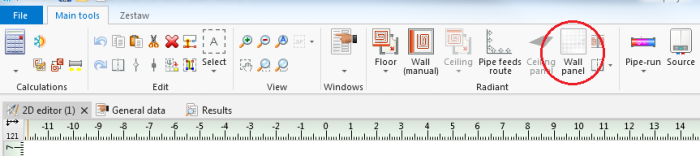
2.Wall panel icon - 1. Insert subsequent panels and adjust their orientation in relation to previous panels using the AUTO and ORTO modes and the Copy/Paste function.
For more information, see: [[{{{link}}}]] Basic components of graphic editing environment - 2. Optimize the relative positions of connection points for the series connections between the panels using a combination of the following tools: Rotate and Flip horizontal, Flip vertical.
- 3. Connect the individual panels in series using the Connect in series function. After selecting Connect in seriesfunction, left click the subsequent panels to be connected and complete the connection by right clicking.

Editing of wall panels data
For thermal calculations according to EN 1264:
- Verify the temperature on the other side of the partition on which the wall panel is located.
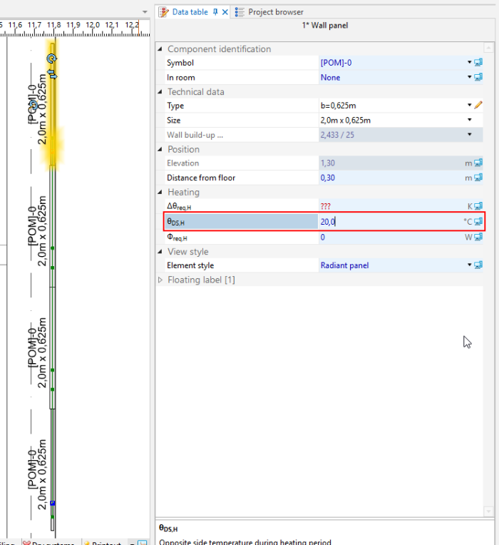
3. Temperature on other side - Verify the partition definitions on which the wall panel is located.
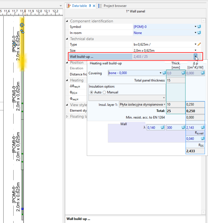
4. Heating wall build-up


Preliminary calculations - diagnostics of heat demand coverage in room
- Make calculations for the radiant heating/cooling scope by selecting the
 icon in the Calculations group.
 - Verify room heat demand coverage in:
- Diagnostics window by viewing the list of warnings
- Results window in List of rooms - heating/List of rooms - cooling tabs
- the hint displayed after position the cursor in the panel area
Data correction to adjust the calculated capacity to the required output
- Adjust data and system parameters:
- supply temperature in general data of the source (θs,H/θs,C rad)
- required temperature drop of the medium in the panel/set of panels connected in series (Δθreq,H).
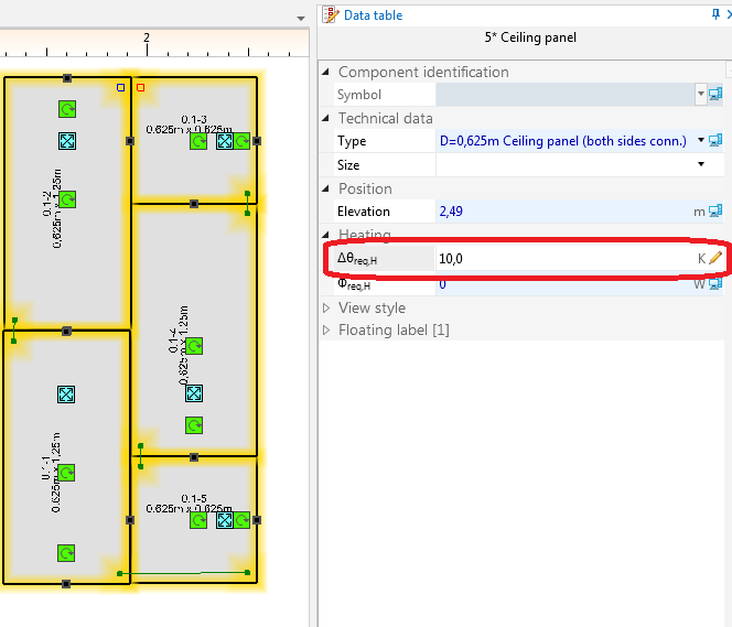
3. . Correction of temperature drop of medium in panel/set of panels connected in series (Δθwym,H) - type, size and number of panels in the system.
- Recalculate the project – verify the effect of changes made on the attained heating output.

Editing the system - appending the drawings with a medium distribution system
- When heat demand coverage results are satisfactory, insert the remaining system components (source, pipe-runs, fittings) and connect them to the panel system.
For more information, see: [[{{{link}}}]] Installation edit
Completing the calculations including system balancing and bill of materials
- Make calculations for the radiant heating/cooling scope by selecting the icon in the Calculations group.
- Verify diagnostics and calculation results, in particular:
- Required parameters of the source - Results window – Results Heating/General results heating tab (likewise for cooling function)
- Flow balancing of the system – Results window – Circuits/Heating/cooling circuits tab
- Bill of materials - Results window – Bill of materials - heating / cooling tab
For more information, see: [[{{{link}}}]] Calculations and diagnostics
Verifying visually the correctness of system arrangement in 3D view
- Open the 3D view window and verify system arrangement, modify component elevations and positions of connection points, if necessary. After making corrections recalculate the project.
For more information, see: [[{{{link}}}]] Verification of the correctness of installation structure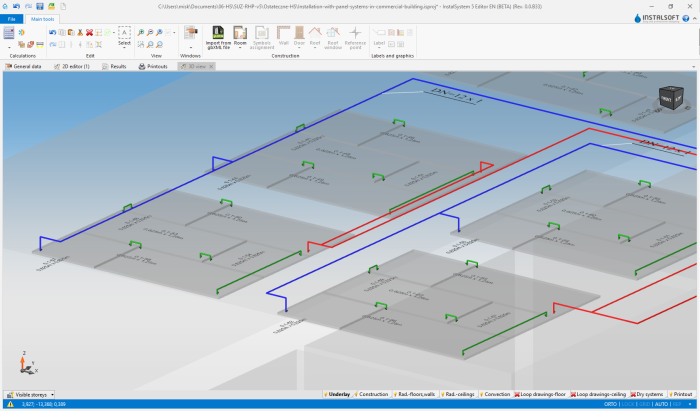
4. 3D view

Preparing drawings for printing/exporting
- Verify the drawing style of the panel in 2D and 3D views and the detail of information displayed in the label. The configuration can be accessed in the General data window.
- Insert and configure the labels of other system components (source, pipe-runs, fittings).
For more information, see: [[{{{link}}}]] Preparation of drawings for export/printing