Heating/cooling zone build-up editor
| Product | InstalSystem 5 |
| Type of article | FUNCTION AND TOOL |
| Source for translation | Version GOLD Rev. 16.0 |
Description
This article describes possibilities of editing structural, thermal and operational data of heating/cooling zones and structural partitions, upon which they are located.
Location in the program
Heating/cooling zone build-up editor is situated in: Data table after having ticked: Heating/Cooling Zone and checked the drop-down list Heating floor build-up \ Heating wall build-up \ Construction of heating/cooling ceiling.

Example of use
Presentation of data in the heating/cooling zone build-up editor
- The Heating floor build-up \ Heating wall build-up \ Construction of heating/cooling ceiling field presents overall thickness of the heating/cooling zone as well as overall thermal resistance.
- Having opened the editor, the user gains access to particular data, on the basis of which overall values are calculated:
- Overal thickness of heating/cooling zone layers.

3. Layer thickness - Thermal resistance of particular layers of a given heating/cooling zone along with structural partition thermal resistance.
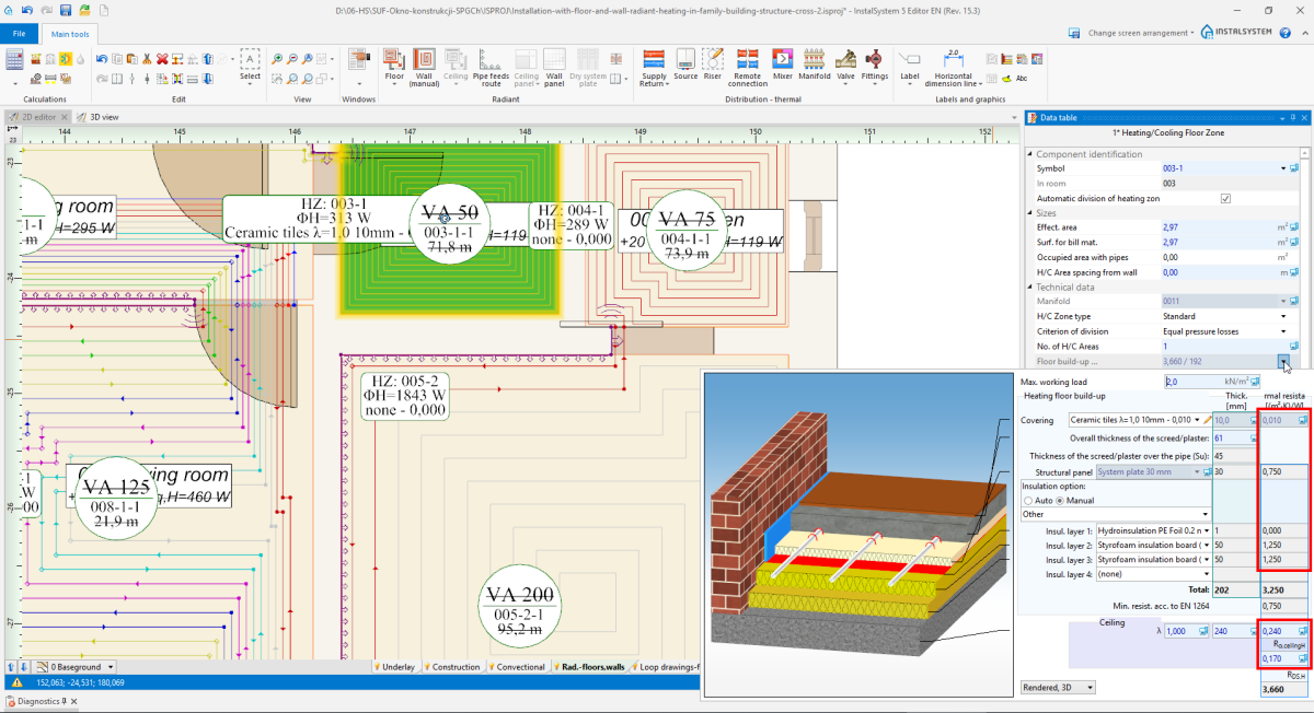
4. Thermal resistance of layer 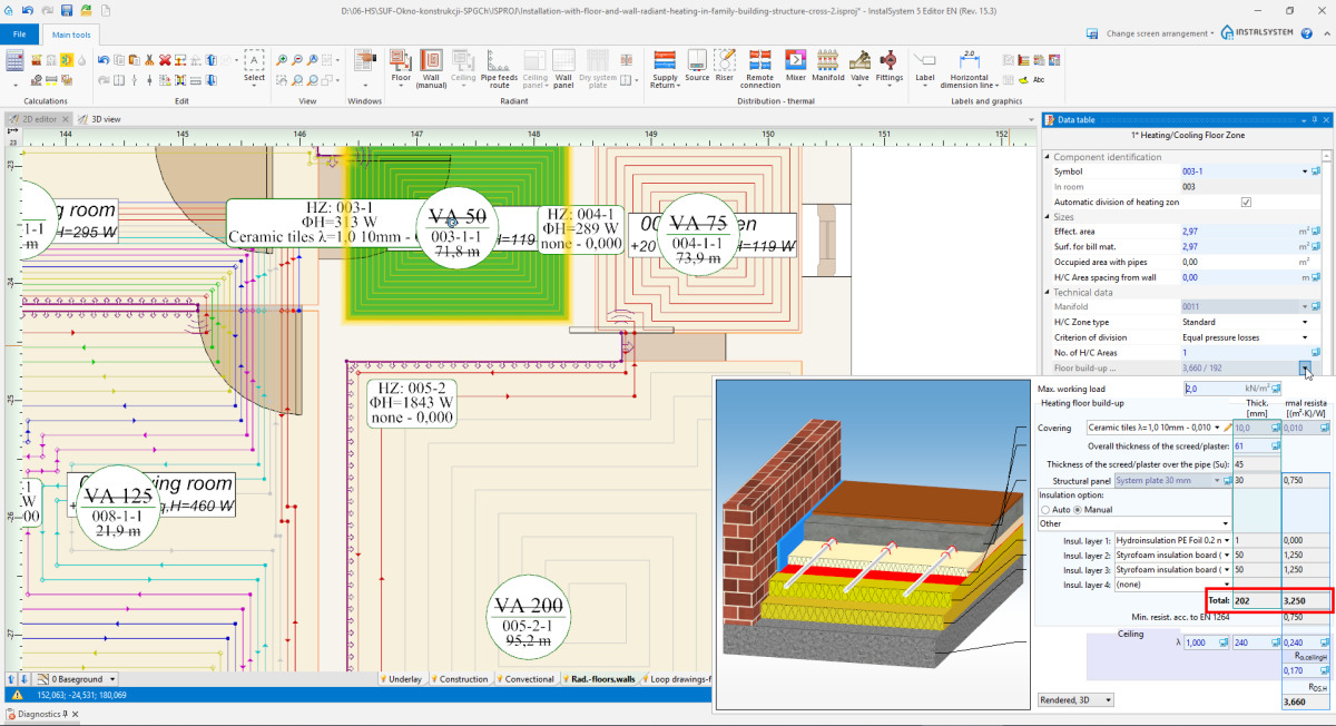
5. Overall constructure thickness i Resistance of layers
- Overal thickness of heating/cooling zone layers.


After data modification in the editor window, it is necessary to recalculate the project to update all values.
Heating/Cooling zone build-up edition
Covering

- Default covering originates from General data for Room type elements.
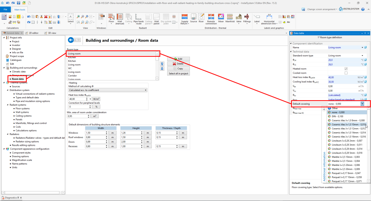
7. Default covering - Covering may be changed for each Heating/Cooling Zone element.
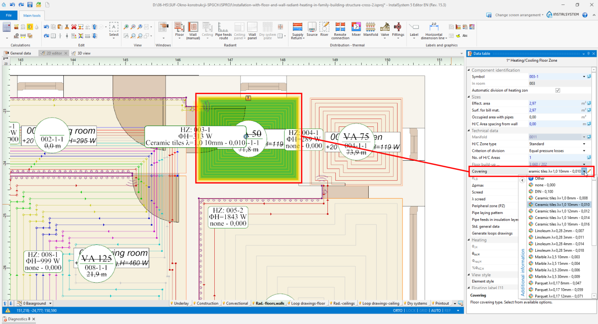
8. Covering


Overall thickness of the screed/plaster

Overall thickness of the screed/plaster, in case of the Auto setting, may change according to the Max. working load value (), within limits allowed by the producer. The user may change thickness, also in the limits allowed by the system producer, while taking into consideration all other system data.
Thickness of the screed/plaster over the pipe Su is always calculated automatically by the program, and it cannot be changed manually.
Structural panel

- The user may change the structural panel if:
- there are more structural panels than one for a given fastening method.
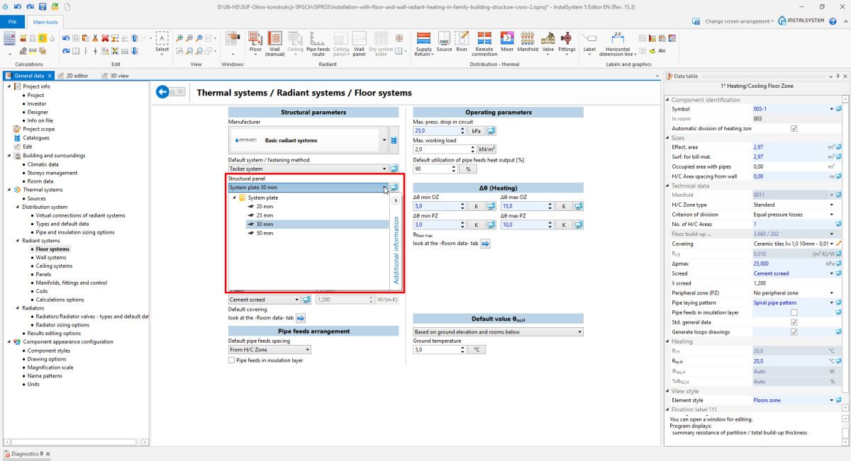
11. Structural panel - choose from General data - In Data table of the element Heating/Cooling Zone, the user ticked off Std. general data - otherwise, the field is available only in the Auto status, with no edition possibilities.
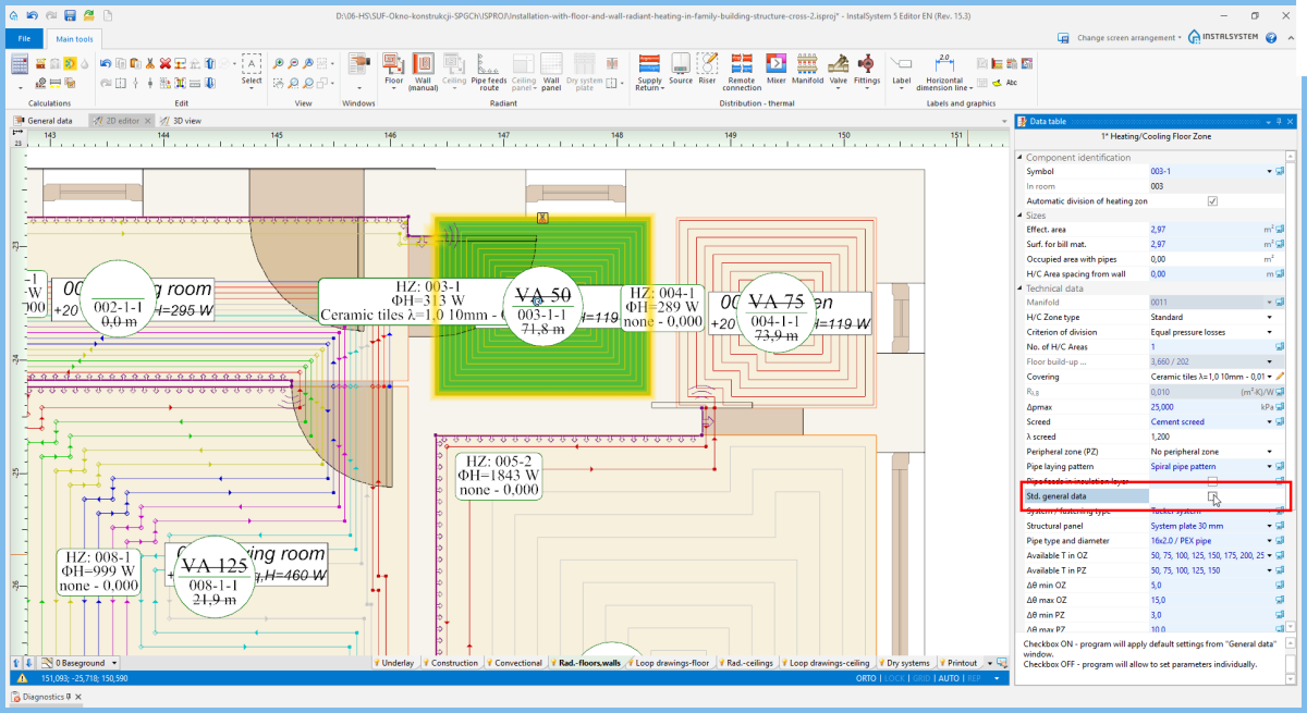
12. Structural panel - selection in Data table


Insulation option

- Auto
The program selects Insulation option with minimal resistance according to EN 1264: 1:2011 2:2013 3,4:2009 5:2008 for a given structural panel and upon the Temperature on other side value.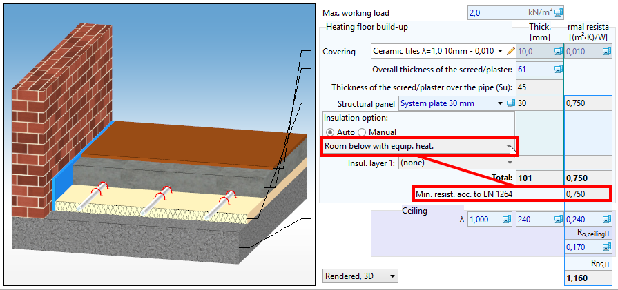
14. Insulation option - Auto - Manual
It is possible to choose Insulation option from the catalogue or to define one's own by choosing particular insulation layers (up to 5 layers).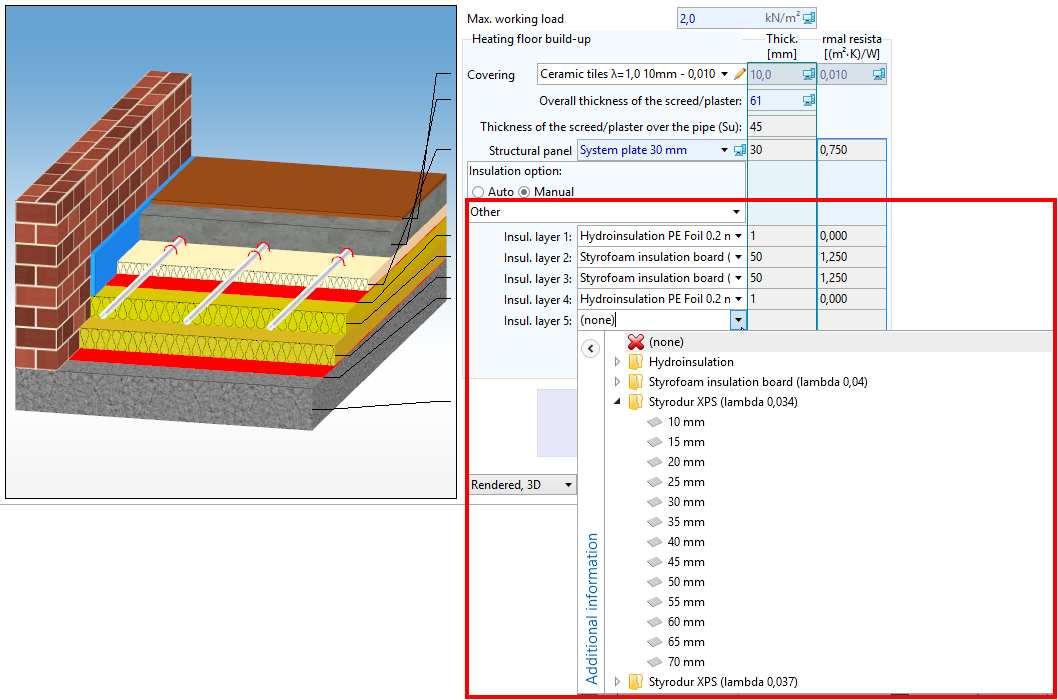
15. Insulation option - Manual


Structure cross section drawing
The user may change the way in which the structure cross section drawing is presented.

Structural and heating partition data editing

- The program does not select elements among Partition definitions from the Thermal calculations of building scope, and they should be corrected manually.
- From General data, only the Lower slab thickness, dflo,l value is drawn.
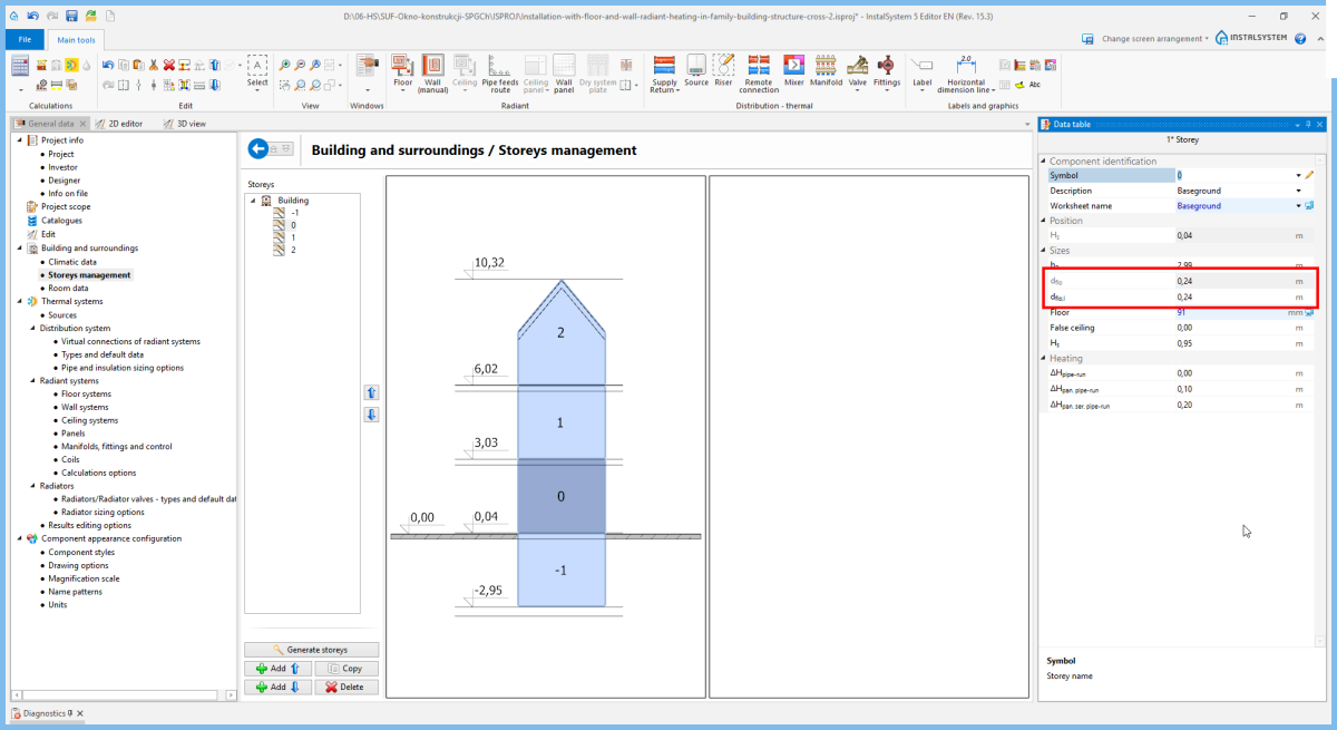
18. Lower slab thickness, dflo,l
